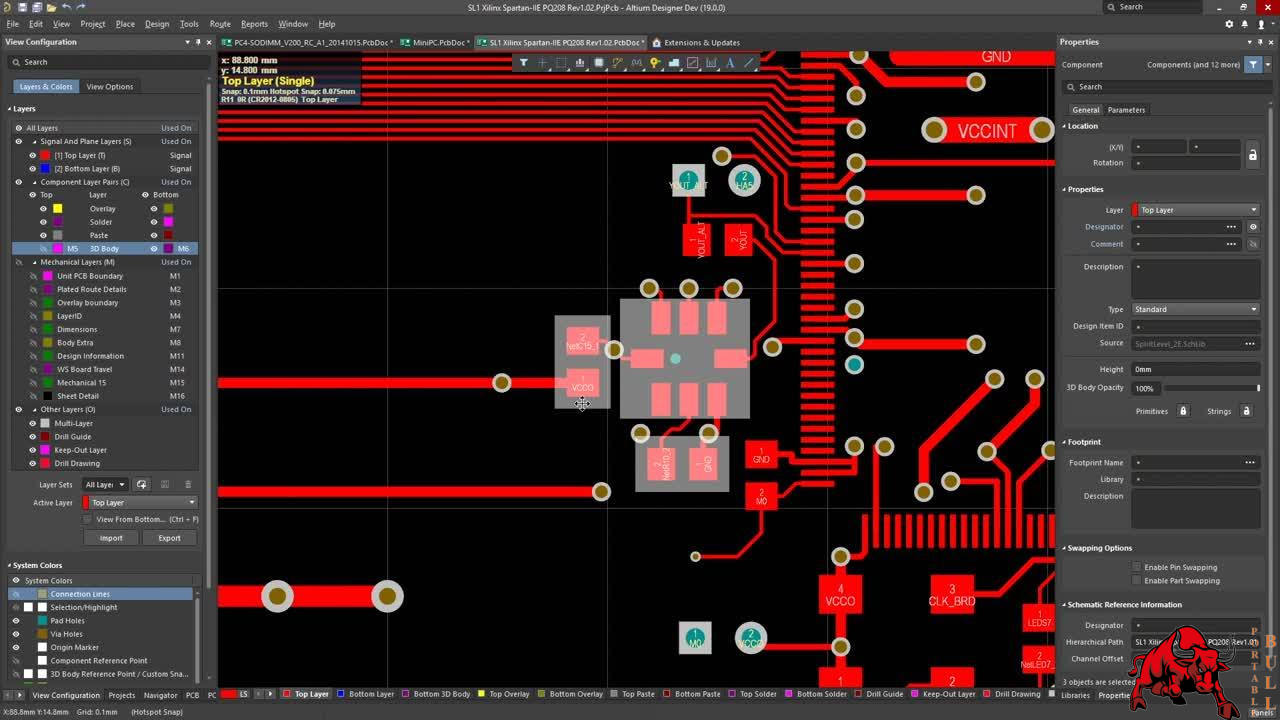

If you could clarify these questions for me, I would greatly appreciate it.ĭesignator: layer used to put component designator in case you don’t want or you can’t print them as silkscreen. The top layer and the top solder layer look identical (except for the color of course) so why do we need both? the designator, the top layer, the top paste, the top solder, and top assembly). For example, I know that the top overlay is for text (the silkscreen), the component center layer is for providing an origin/zero point/reference point for the component, the top courtyard is for declaring that "this component needs this much clearance to ensure that it doesn't collide with other components".īut I am not really sure what the other layers are for (i.e. Some of them, I already have a general idea on. I was wondering if you could give a description of what each of these layers are, what their purpose is, how it is linked to the actual, physical pcb, etc. In this link, you will see a design, and you'll see the various layers that make up that design. Would you please share your knowledge on these layers? I have posted some images here as a reference. However, Altium seems to have many more layers than what is actually physically present on a pcb. The soldermask is applied on top of the copper, and the copper can form the signal/ground layers. This material is what gives a pcb its distinct color. There is also the soldermask which is a dielectric material used to ensure that different pcb traces won't touch each other. For a physical pcb, I know that there is the silk-screen layer (which would be the top overlay layer in Altium) and this is where text is written and graphics is shown.

I am somewhat familiar with how a pcb is fabricated, however I am not quite sure how the various layers in Altium corresponds to the actual layers of a pcb. For instance, there is the "top layer", "top solder", "top paste", etc. However, I find that I am confused as to how the pcb design process works in terms of the various layers that are used in Altium. Hi all, I am new to PCB design and I am learning to use Altium designer.


 0 kommentar(er)
